UART protocol is used for serial communication and two wires are used for communication in this protocol. The transmission speed and data format are defined before the communication in the UART protocol. And data is transmitted in the form of packets.
Basics of UART Protocol
UART protocol stands for Universal Asynchronous Receiver Transmitter protocol. And UART protocol is used for serial communication. In this, there is a connection of two wires one is for transmission and another one is for reception. Configuration of the speed of transmission and data format is also done here. So the speed of transmission and data format is defined before the communication. And it is an asynchronous protocol as no click is defined in this.
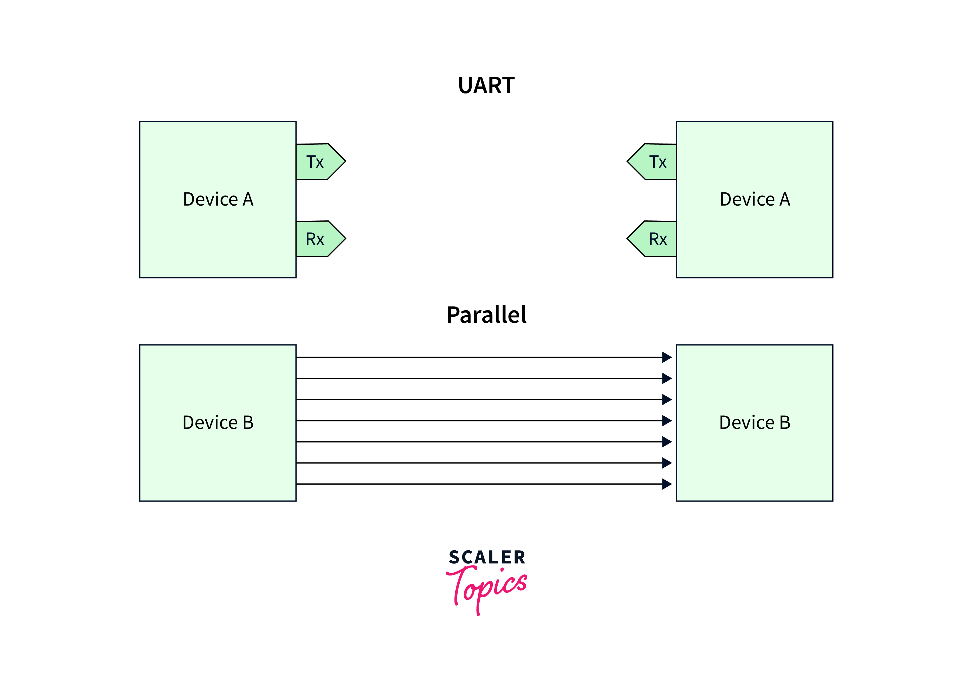
Here we have two devices device A and device B, and device A has a transmitter and receiver pin and device B has a receiver and transmitter pin. Connection of device A transmitter should be created with the device B receiver pin. The connection of the device B transmitter should be created with the device A receiver pin. We need two wires for the connection.
- When device A wants to transmit data to device A then it will share data via its transmitter’s pin and device B’s receiver will receive the sent data.
- And if device A desires to receive the data then it will receive it on the receiver pin sent by device B via its transmitter’s pin.
If we compare UART serial communication with parallel, then it can be found that multiple buses are needed for parallel. UART protocol is better than parallel communication in terms of the complexity of bus line numbers but on the other hand, parallel communication is better than serial in terms of speed.
So parallel communication is used when there is a requirement of good speed for the data communication, but for applications with low speed, UART protocol is considered the best option with less complexity in the bus.
UART protocol configuration is completed before the data transmission, the connection is established between both devices using the protocol, and both devices should the transmission speed of data.
- Firstly, the speed of both devices is defined, and then the data transmission speed for both devices is configured which is known as the baud rate. Here both the communicating device has the same baud rate, if they have different baud rate then the device can not understand the speed and rate of incoming data.
- After that, the length of the data is configured. Data length is also configured and fixed for both devices. For example, if an 8-bit data size is configured for device A, then the same data size must be configured for device B.
UART Data Format
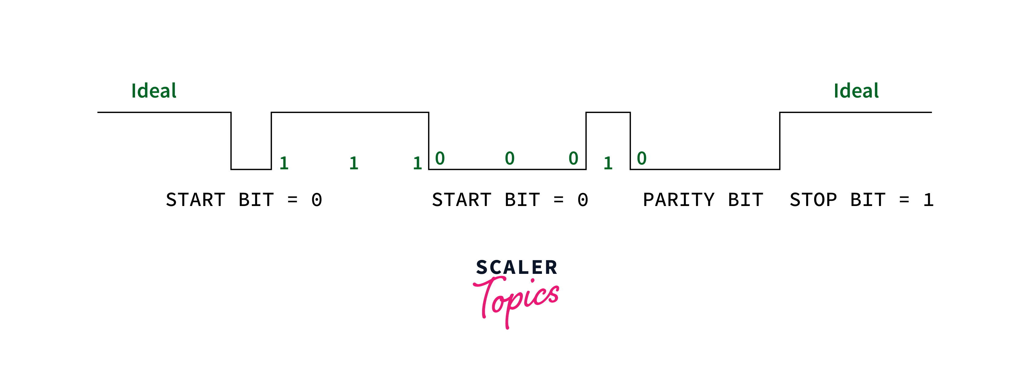
Let us suppose device A is transmitting data to device B.
- The data is sent by the transmitter of device A to the device B receiver, then the logic will be high. The start bit with logic 0 is sent by which device B came to know some device is trying to start communication.
- Now both devices will have the configuration with the same speed. So data can be sent by device A after sending the start bit.
- Let us assume data of 8 bits will be sent and device B has received those sent 8 bits. The parity bit is optional to send but sending the parity bit is considered as a good option.
- The parity bit is used to check whether the correct data is received from the sender or not. Let us assume 1 1 1 0 0 0 1 0 data is sent.
- In this data there are 4 ones, which is an even number, so for this data we have even parity and we have assigned logic 0 for that.
- But now let us assume data received by the receiver is 1 1 1 1 0 0 1 0 and one zero is modified to one during the data transmission.
- And now the received data has an odd number of ones, which means it has odd parity, which tells the receiver that the data received is not correct means it is modified during transmission.
UART Data Transmission

The transmission mode in UART protocol is in packet form. The connection established between the sender and receiver involves aerial packet creation and physical hardware line control. The start bit, data frame, parity bit, and end bit are involved in the packet of the UART protocol.
Start Bit
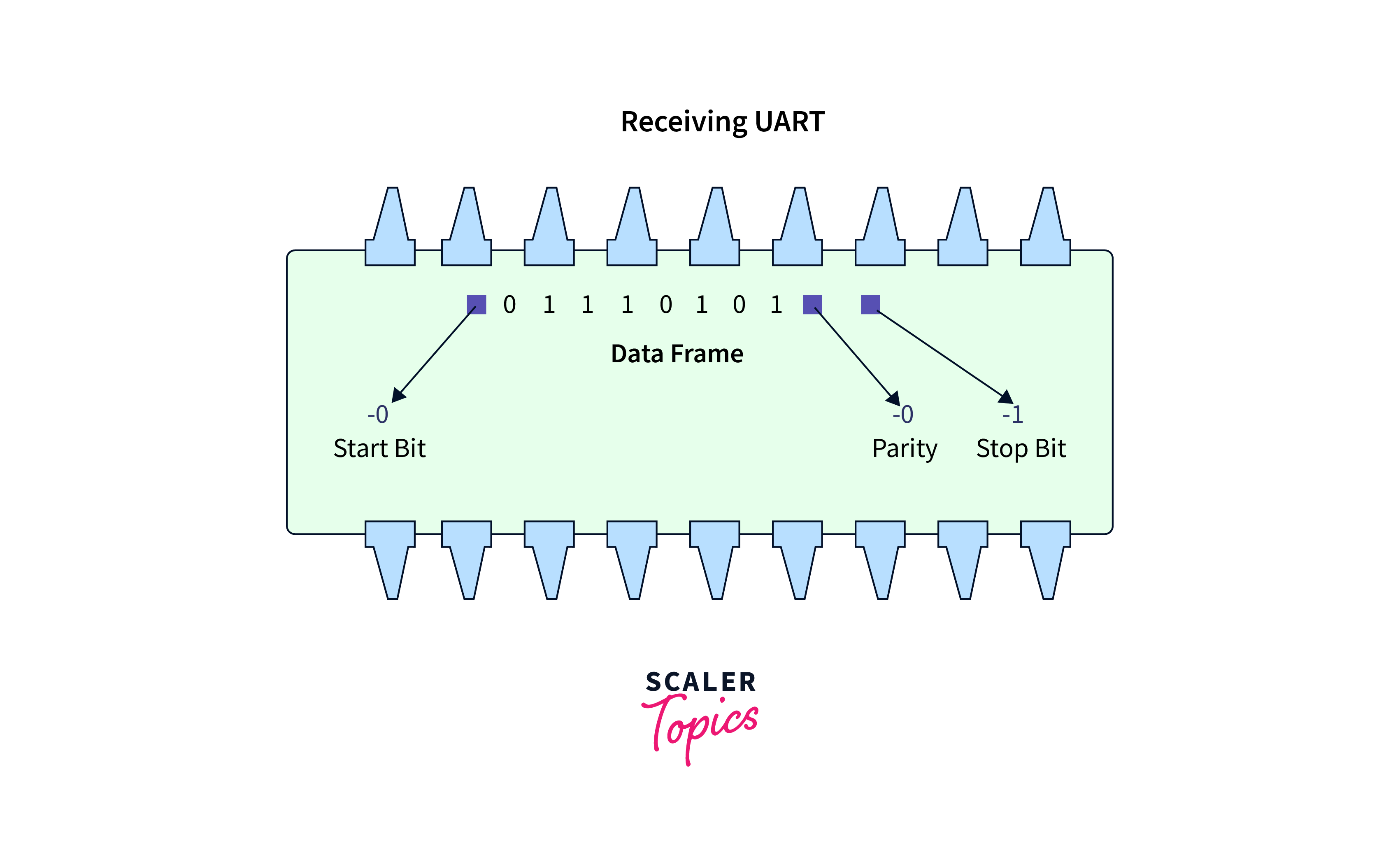
When there is no data transmission then the voltage level of the data transmission line of UART is high. The transmission line is pulled from high to low by the transmitting UART for one clock cycle to start the data transmission. When the transition of voltage from high to low is detected by the receiving UART, it starts reading data frame bits at the baud rate frequency.

Data Frame
The actual data to be transmitted is in the data frame. Its length can be 5 bits and the maximum length can be 8 bits if a parity bit is added in the data. Data length can be 9 bits without a parity bit. Mostly, the least significant bit of data is transmitted first.

Parity
The parity bit is used by the receiving UART to decide whether the data received is correct or not, which means detecting any modifications that have occurred in data bits during transmission. During transmission, transferring data over long distances, mismatched baud rates, and electromagnetic radiation are some reasons for the modification of data bits.
- After receiving the data, UART reads the bits of data, and it checks the number of 1 bits in the data, and looks at whether the count of the number of 1 bit is even or odd.
- If the parity bit in the data is 0, then it means the data has even parity, and then the count of the number of 1 bits of data must also be an even number.
- If the parity bit in the data is 1, then it means the data has odd parity, and then the count of the number of 1 bits of data must also be an odd number.
- When the 1-bit count of data is according to the parity bit of received data then the receiving UART comes to know that no error has occurred in data during transmission.
- But if the 1-bit count is odd and the parity bit is 0 or the 1-bit count is even and the parity bit is 1 then receiving UART comes to know that the data bits are modified during transmission.

Stop Bits
The transmission line is transmitted from low to high voltage by the sending UART to tell the data packet end.

Steps of UART Transmission
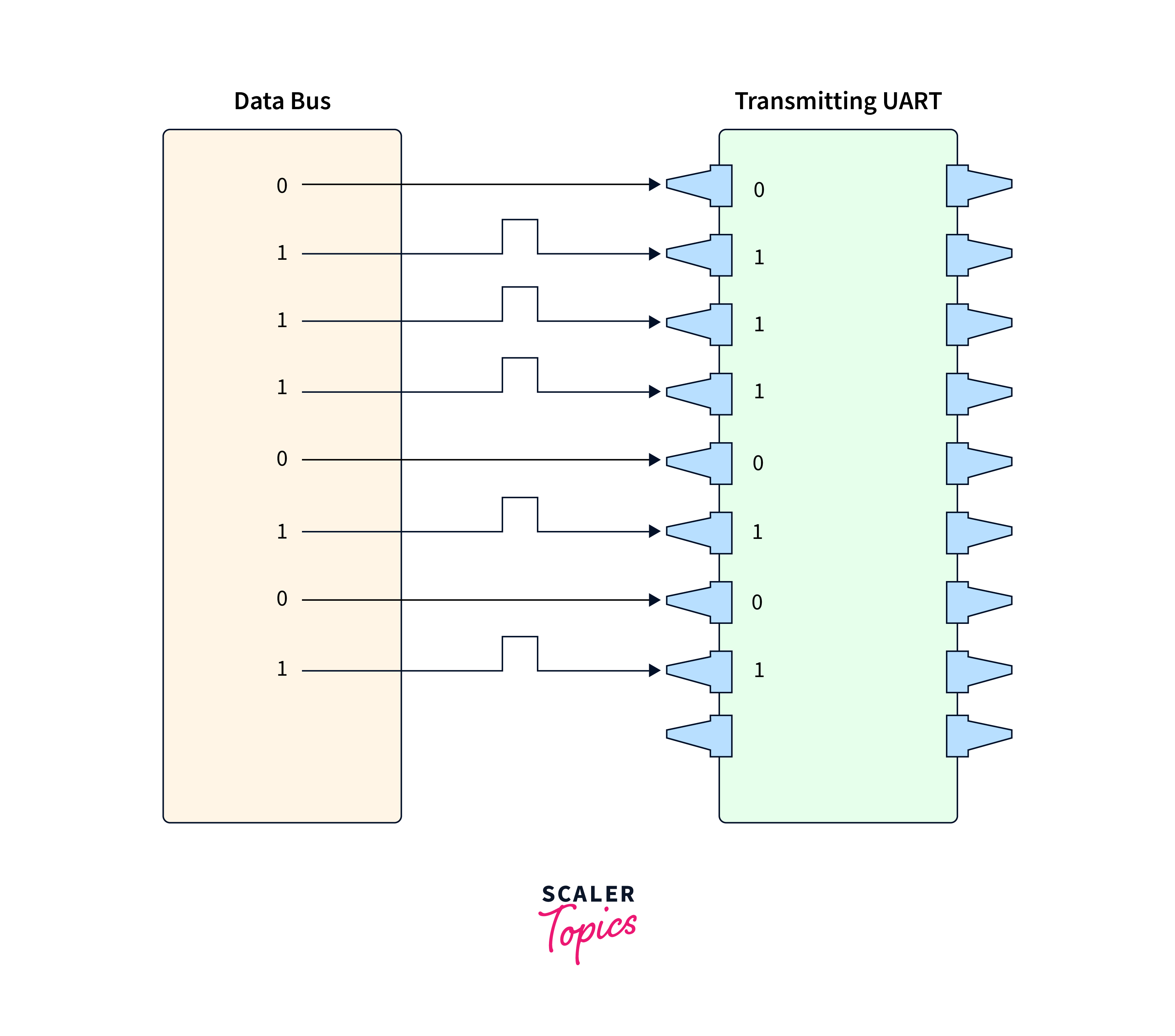
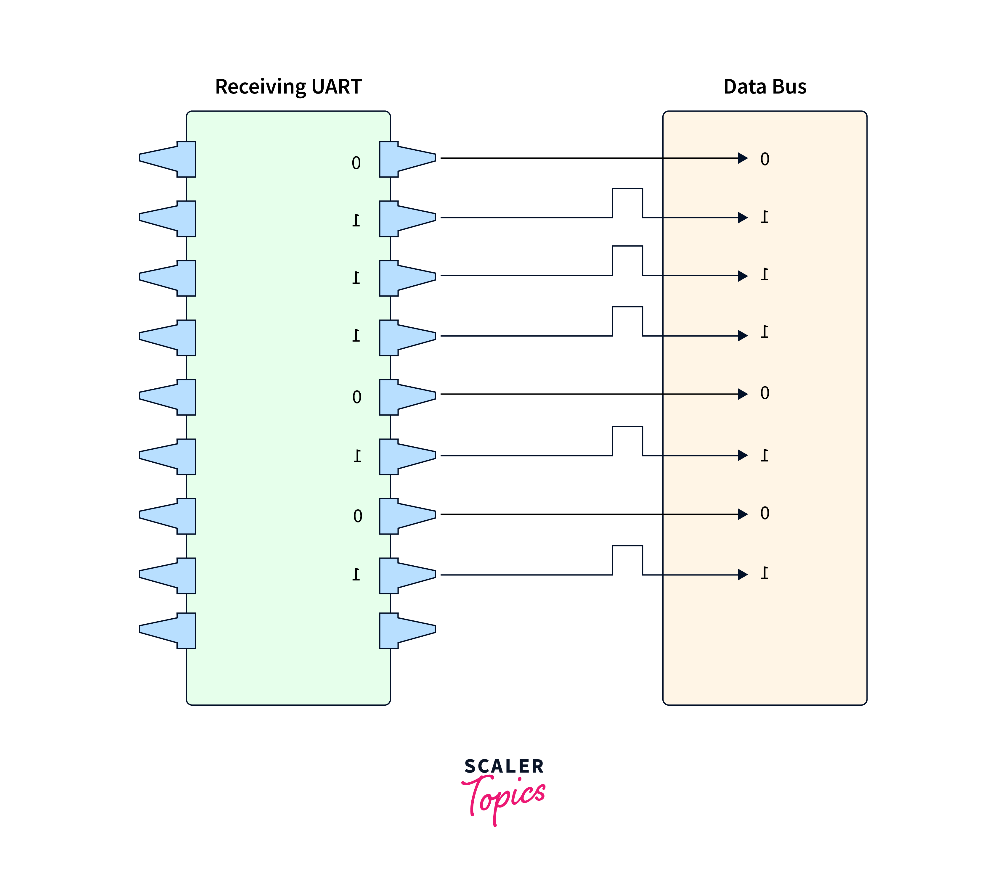
Step 1: Firstly parallel data is received by the sending UART from the data bus.
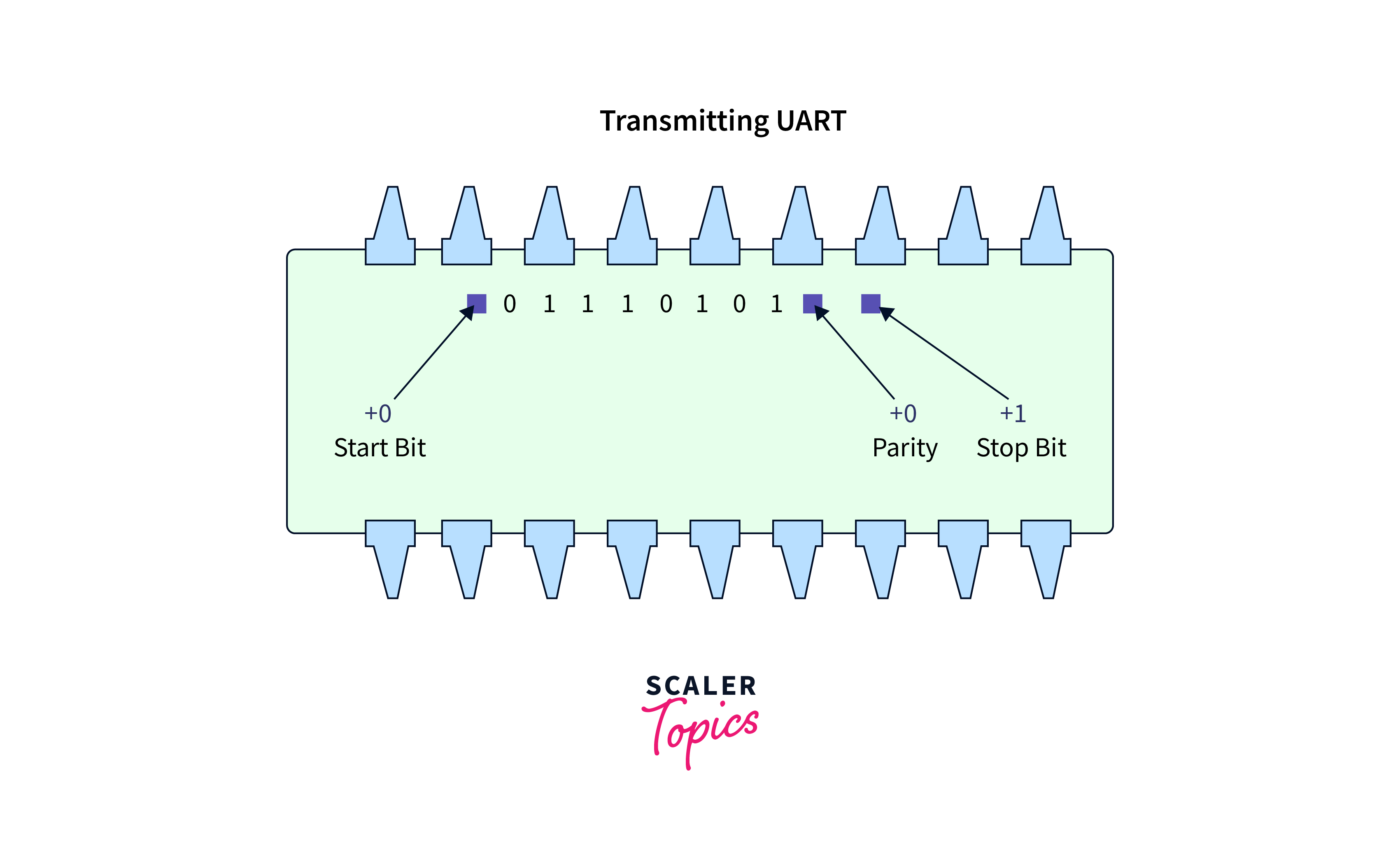
Step 2: Then the start bit, parity bit, and end bit are added by the transmitting UART in the data frame.
Step 3: Transmitting UART sends the complete data from the start bit till the end bit to the receiving UART serially. The data line is sampled by the receiving UARt at the baud rate already configured.
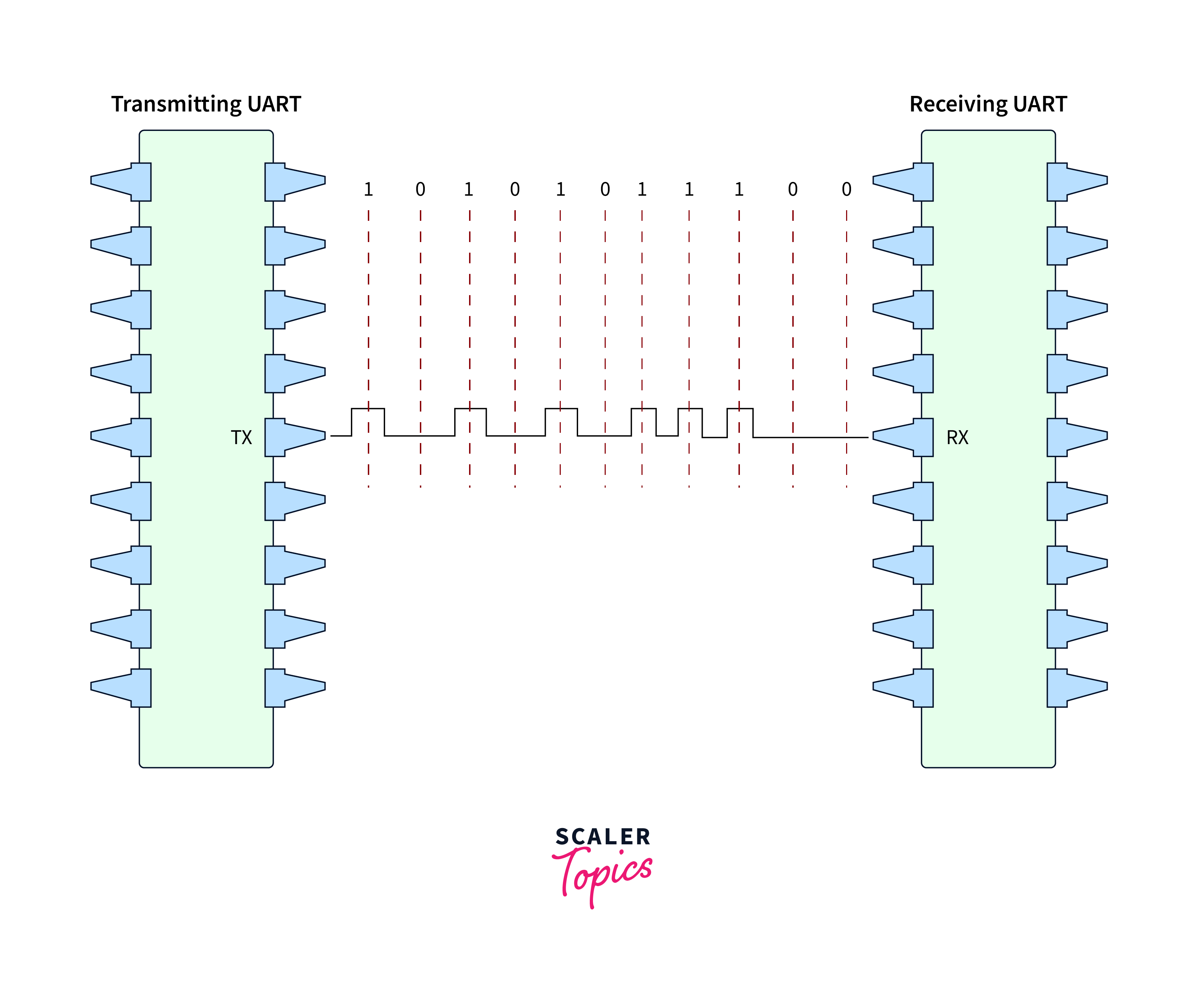
Step 4: Start bit, parity bit and stop bit are discarded by the receiving UART from the data frame.
Step 5: Now the serial data is converted back to the parallel data by the receiving UART and transmits data to the data bus.
UART Operations
While any hardware configuration protocol is used, checking the hardware reference manual and data sheet is considered the prerequisite.
Follow the steps given below:
Step 1: Check the interface of the device datasheet.
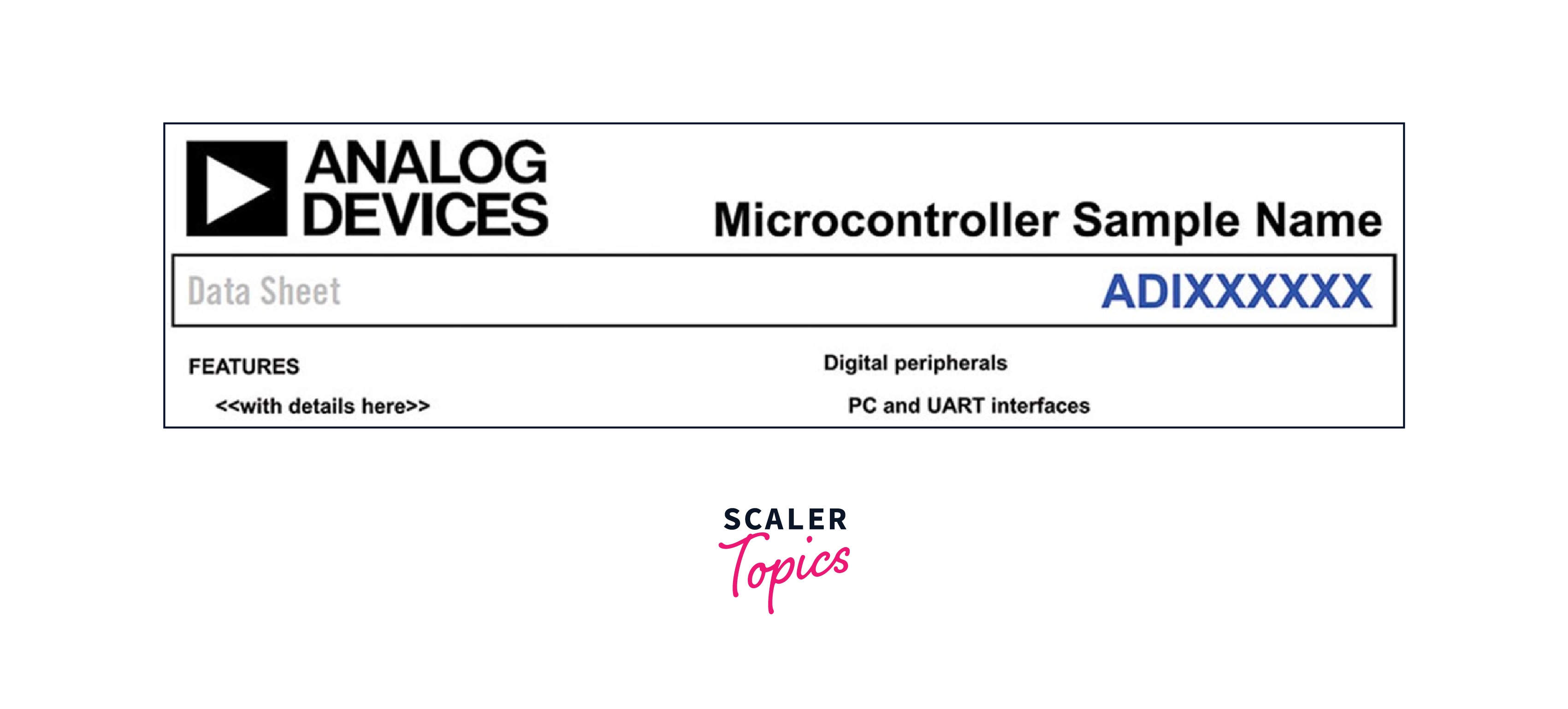
Step 2: Check UART PORT specific details which include parity bits, length of data bits, operation mode, and stop bits.
A full duplex UART port is provided by the sample MCUs which is completely compatible with the UARTs of PC standard. A simplified UART interface is provided by the UART port for other hosts or peripherals which supports serial data asynchronous, DMA, and full-duplex transmission. 5 to 8 bits are supported by the UART port, and one or none bit is for the parity. One and a half or 2 bits are used for the frame termination.
Step 3: Check the details of the UART operation such as the configuration of the baud rate. The sampling formula given below is used for the configuration of the baud rate. And this formula changes based on the microcontroller.
Below are UART operations sample details
- 5 to 8 bits for the data
- 1, 2, or 1 and ½ for the stop bits.
- Even or odd or none parity.
- Programmable oversample rate by 4, 8, 16, 32
- Baud rate = PCLK/((M + N/2048) × 2OSR + 2 × DIV
Step 4: Ensure that you have checked the peripheral clock (PCLK) for the baud rate. DIVN, DIVM, DIV, and OSR changes as per the device.
Step 5: Next check the detailed register for the configuration of UART.
Step 6: Check the details under every register and put values for baud rate computation, then start UART implementation.
Use Cases
There are multiple use cases of the UART protocol. Some of them are given below:
- Debugging: During early detection of errors is necessary. In this scenario, UART helps in this situation by capturing messages from the system.
- Manufacturing function-level tracing: Logs are considered very important in the process of manufacturing. Functionalities are determined by notifying the operators about what is going on in the manufacturing line.
- Client or customer updates: Software updates are considered good and very important. Dynamic and complete hardware along with the capability of software updates is considered an important part of the complete system.
- Verification/testing: Product verification before the manufacturing process completion is very helpful in providing the product with the best quality to the customers.
Advantages and Disadvantages of UART Protocol
Advantages
- Two wires are used only.
- No requirement for a clock signal.
- Error detection can be done using a parity check.
- Widely used protocol.
- Well documented
- Data packet structure can be modified till both the communicating ends are set up for it.
Disadvantages
- Maximum size of the data frame can be 9 bits.
- Many masters and many slaves are not supported.
- Every UART baud rate must be less than 10% of each other.
Conclusion
- UART protocol stands for Universal Asynchronous Receiver Transmitter protocol. And UART protocol is used for serial communication.
- The transmission mode in UART protocol is in packet form. The connection established between the sender and receiver involves aerial packet creation and physical hardware line control.
- Start bit, data frame, parity bit and end bit are involved in the packet of the UART protocol.
- During any hardware configuration protocol used, checking the hardware reference manual and data sheet is considered the prerequisite.
- Debugging, Manufacturing function-level tracing, Client or customer updates and Verification/testing are the use cases of UART protocol.
- Two wires are required, No requirement of clock signal, etc. are some advantages of UARt protocol.
- The maximum size of the data frame can be 9 bits is one of the disadvantages of the UART protocol.