Fragmentation is a process that divides packets into smaller pieces (fragments) so that the resulting pieces can travel across a link with a smaller maximum transmission unit (MTU) than the original packet size. The network layer fragments data when the maximum size of a datagram exceeds the maximum size of data that can be retained in a frame, i.e., its Maximum Transmission Unit (MTU). So that data flow is not impeded, the network layer separates the datagram received from the transport layer into fragments.
:::
:::section{.main}
What is Fragmentation in Networking?
IP fragmentation is a process that divides packets into smaller pieces (fragments) so that the resulting pieces can travel across a link with a smaller maximum transmission unit (MTU) than the original packet size. The receiving host reassembles the fragments.
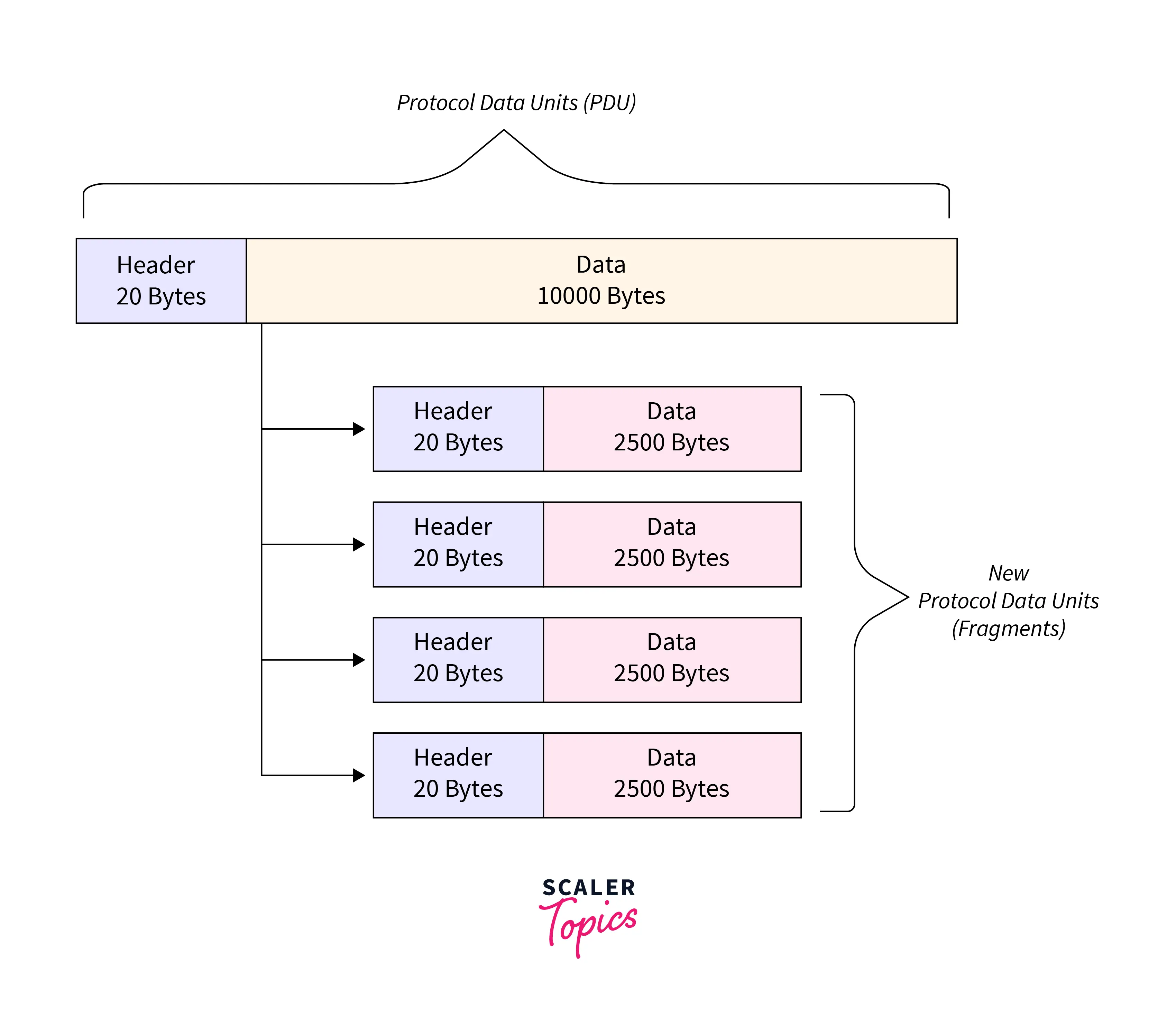
An IP packet cannot be larger than the maximum size allowed by that local network when sent over the network by a host. The network’s data link and IP Maximum Transmission Units (MTUs), which are typically the same, determine its size. 1500 byte MTUs are standard for modern Ethernet-based office, campus, or data center networks.
However, packets initially delivered across a network with one MTU may need to be routed over networks with a smaller MTU (such as a WAN or VPN tunnel). If the packet size in these circumstances is greater than the lower MTU, the data in the packet must be fragmented (if possible). This indicates that it is divided into fragments carried in brand-new packets (fragments) that are equal to or less than the lower MTU. This is known as fragmentation, and when the fragments arrive at their destination, the data is usually put back together.
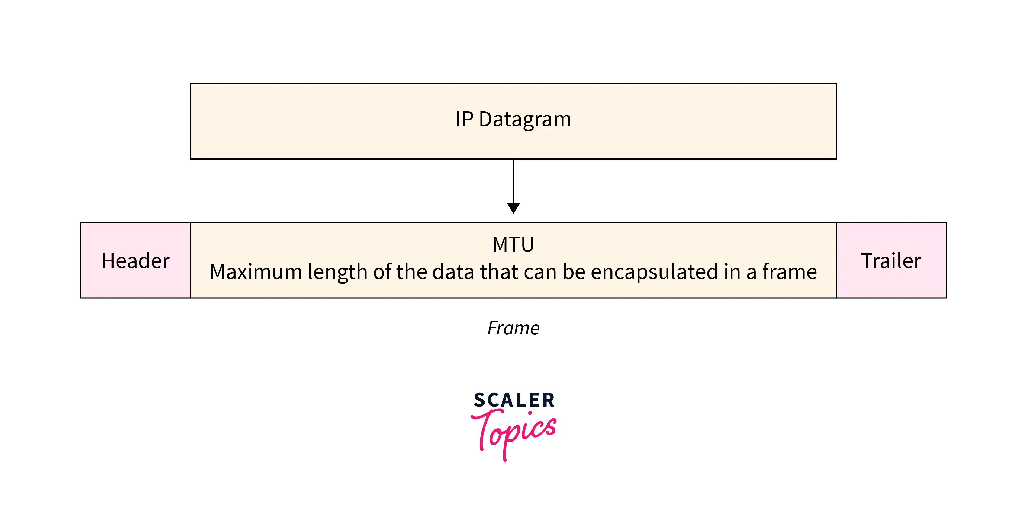
Some points related to the fragmentation:
- The maximum size of an IP datagram is $2^{16} – 1 = 65, 535$ bytes, as the IP header has a total length of
16 bits. - It is performed by the network layer at the destination side, typically at routers.
- Due to intelligent (excellent) segmentation by the transport layer, the source side does not require fragmentation. Specifically, the transport layer looks at the datagram and frame data limits and segments the data so that it can easily fit in a frame without the need for fragmentation.
- The receiver uses the identification (
16 bits) field in the IP header to identify the packet. The identification number for each frame fragment is the same. - The receiver uses the fragment offset(
13 bits) field in the IP header to identify the series of frames. - The extra header created by fragmentation results in overhead at the network layer.
:::
:::section{.main}
Process of Fragmentation
RFC 791 specifies IP packet fragmentation, transmission, and reassembly mechanism.
RFC 815 specifies a streamlined reassembly algorithm. The Identification field in the IP header, along with the foreign and local internet addresses and the protocol ID, and the Fragment offset field in the IP header, coupled with the Don’t Fragment and More Fragments flags, are used for fragmentation and reassembly of IP packets.
If a receiving host receives a fragmented IP packet, it must put the packet back together and send it to the higher protocol layer. Reassembling is supposed to occur in the receiving host, but in reality, it might be carried out by an intermediate router. For instance, network address translation (NAT) can need to reassemble fragments to translate data streams.
:::
:::section{.main}
Fields in IP Header for Fragmentation
- Identification Field (16 bits):- It is used to recognize fragments of the same frame.
- Fragment Offset Field (13 bits):- It is used to determine the sequence of pieces in the frame. It often denotes the number of data bytes preceding or preceding the fragment. Maximum fragment offset possible = $(65535 – 20) = 65515$, where
65535is the maximum datagram size, and20is the minimum IP header size. As a result, a fragment offset requires $ceil(log265515) = 16$ bits, yet the fragment offset field only has13bits. So, to efficiently represent the fragment offset field, we must scale it down by $2^{16}/2^{13} = 8$, which functions as a scaling factor. As a result, all fragments except the last should have data in multiples of8, so that fragment offset belongs toN. - More Fragments Field (MF):- This field tells if there are more fragments ahead of this fragment, i.e., if
MF = 1, there are more fragments ahead of this fragment, and if MF =0, it is the last fragment. - Don’t Fragment Field (DF):- If we don’t want the packet to be fragmented, we set DF to
1.
:::
:::section{.main}
IP Fragmentation Examples
Now let’s understand the concept of IP fragmentation with the help of an example.
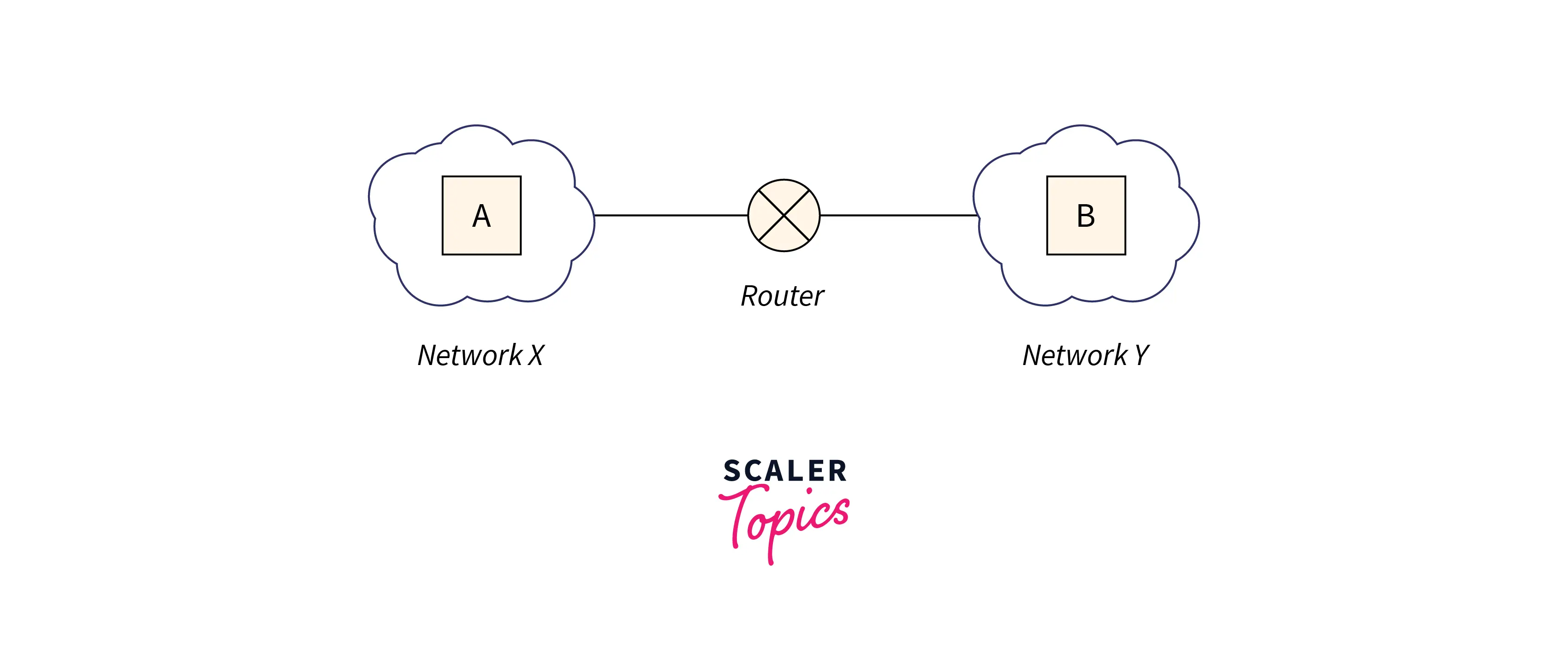
- In
network X, a host named A has an MTU of520bytes. - In
network Y, a host named B has an MTU of200bytes. Host Aofnetwork Xwants to send a message tohost Binnetwork Y.
Assume a router gets a datagram from host A that contains-
- The length of the header is
20bytes. - The length of the payload is
500bytes. - The whole length is
520bytes. - The DF bit is set to
0.
The router now operates in the following steps:
Step 1:
The router looks through the datagram and discovers:
- The datagram has a size of
520bytes. Network Yis the destination, and its MTU is200bytes.- The DF bit is set to
0.
The router concludes:
- The datagram’s size exceeds the MTU.
- It must therefore break the datagram into fragments.
- DF bit has been set to
0. - Therefore, it is acceptable to create datagram fragments.
Step 2:
The router determines the amount of data that should be transmitted in each fragment.
The router is aware of:
- The destination network’s MTU is
200bytes. - Therefore, any fragment can only have a maximum total length of
200bytes. - The header will take up
20bytes out of the total200bytes. - Thus,
180bytes is the maximum amount of data that can be delivered in any fragment.
The router uses the following rule to determine how much data will be delivered in a single fragment:
Rule:
The quantity of data delivered in a single fragment is chosen in such a way that-
- It is as large as feasible but less than or equal to MTU.
- It is a multiple of 8, so a pure decimal value for the fragment offset field can be obtained.
:::
:::section{.tip}
- The final fragment is not required to contain data in multiples of
8, though. - This is because it need not determine the fragment offset value for any other fragment.
:::
:::section{.main}
Following the above rule,
- The router determines a maximum of
176bytes of data that can be sent in one fragment. - This is because it is the highest figure that is less than MTU and a multiple of
8.
Step 3:
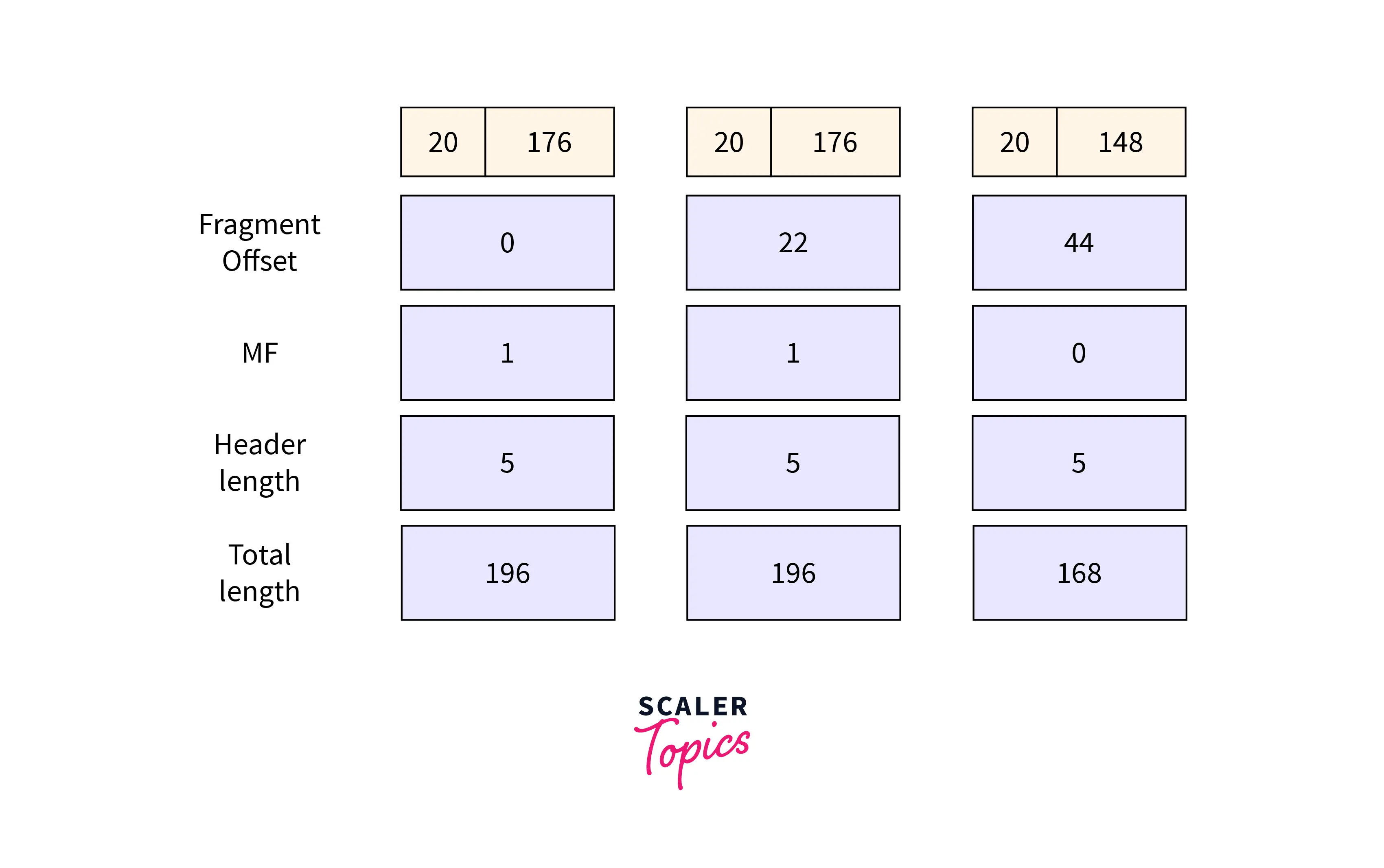
The router splits the original datagram into three parts where:
- The first fragment contains data =
176 bytes. - The second segment has data =
176 bytes. - The third fragment contains data =
148 bytes.
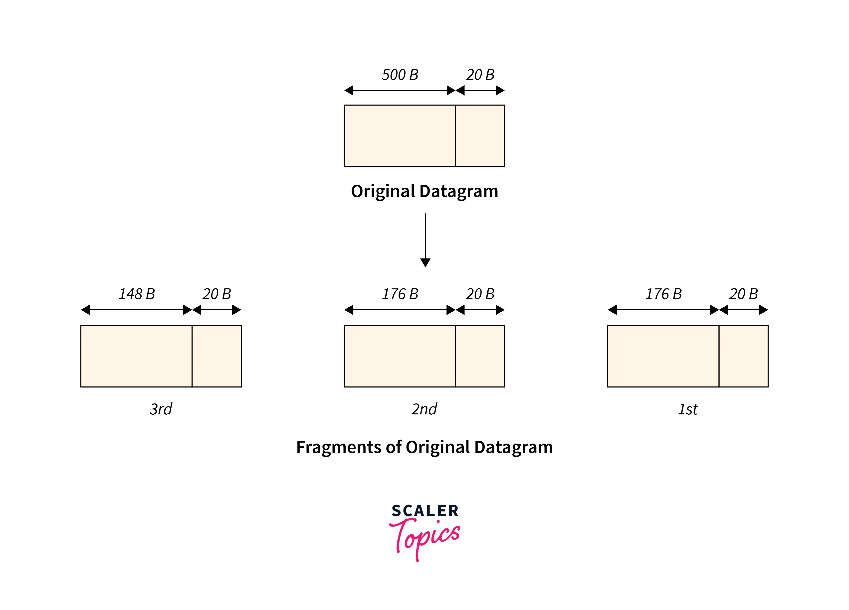
Each fragment’s IP header contains information:
Header information of 1st fragment
- Field value for header length = $20 / 4 = 5$.
- Total length field value = $176 + 20 = 196$.
- MF
bit = 1. - The value of the fragment offset field is
0. - The header checksum is updated.
- The identification number is the same as the original datagram.
Header information of 2nd fragment
- Field value for header length = $20 / 4 = 5$.
- Total length field value = $176 + 20 = 196$.
- MF
bit = 1. - The value of the fragment offset field is $176/8 = 22$.
- The header checksum is updated.
- The identification number is the same as the original datagram.
Header information of 3rd fragment
- Field value for header length = $20 / 4 = 5$.
- Total length field value = $148 + 20 = 168$.
- MF
bit = 0. - The value of the fragment offset field is $(176 + 176)/8 = 44$.
- The header checksum is updated.
- The identification number is the same as the original datagram.
The router retransmits all the fragments.
Step 4:
On the destination side,
- The receiver receives three datagram fragments.
- To get the original datagram, the reassembly algorithm is used to combine all of the fragments.
:::
:::section{.main}
Why is Fragmentation Needed?
The datagram generated by the network layer at the source computer must traverse many networks before arriving at the destination computer. Typically, the source computer favors sending large datagrams. This is because if the datagram is broken up into smaller pieces, the header will be repeated for each datagram unit. The header is repeated for every fragmented datagram, wasting network bandwidth.
However, each network has a cap on the largest packet size it can send during this occurrence. Even worse, the source computer is unaware of the packet’s route to get to its destination. It cannot, therefore, determine how small each fragmented datagram must be. The reasons for fragmenting a large datagram into a small fragmented datagram are listed below:
- The capacity of data is limited by the hardware and operating system employed.
- Conformity with national and international norms.
- Each network’s protocols allow for different packet sizes.
- Large packets occupy the network for a longer time than small packets.
- Reduce the mistakes caused by retransmission.
:::
:::section{.main}
What is Datagram?
A datagram is the smallest data transmission unit in a connectionless communication system. Datagrams are data packets that contain enough header information to be routed separately to the destination by all intermediate network switching devices. Since datagrams are used for communication, these networks are known as datagram networks. They can be found in packet-switching networks.
A datagram is a data packet at the network layer. The network layer gets the data from the upper layer and encapsulates it with a header. So, each datagram now consists of data and a header containing information about the data and the services involved.
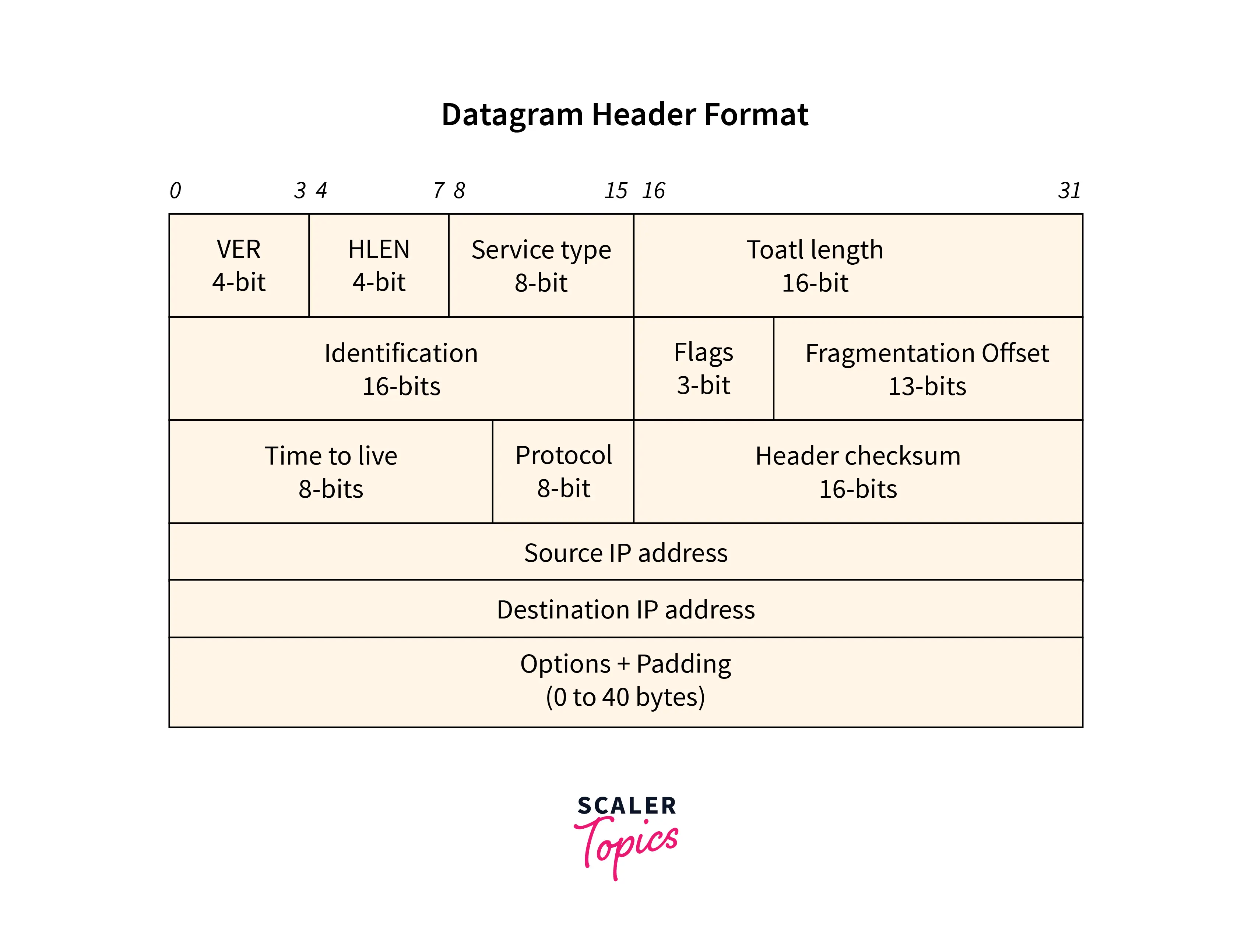
The datagram’s header, which can be between 20 and 60 bytes long, contains:
- Details about the protocol version being used.
- The length of the header (which varies).
- The kind of service used to handle the datagram.
- The overall length of the datagram.
:::
:::section{.main}
Fragmentation of Datagram
Let’s have a look at the step-by-step process of datagram fragmentation:
- Every LAN or WAN network has a restriction on the size of the packets that can be transmitted. The datagram is fragmented if it exceeds this size limit and is created at the network layer. The data is the only entity in the datagram that is fragmented. The datagram’s header is repeated for each fragmented datagram to ensure that the information inside the header is kept intact even after fragmentation.
- The datagram is fragmented at both the source computer and every router it goes through on its way to the destination. The network layer delivers the fragmented datagram to the data link layer, where it is encapsulated in frames and routed to the following router.
- The protocol employed by the physical network from whence the frame has arrived determines the format and size of the received frame at each router. To send the datagram to the following router, the router decapsulates the datagram from the received frame, processes it, and then re-encapsulates it. The size and format of the forwarded frame are determined by the physical network over which the frame must travel to reach the next router or target computer.
- Maximum Transfer Unit (MTU) refers to the maximum number of bytes in a datagram that can be transferred across a physical network. On the other hand, the source computer has no idea which path the frame will take to reach the target computer.
- As a result, it cannot determine how short the packet needs to be to get through all routers without fragmenting. Even if the source computer somehow learns the packet’s MTU, the packet may nevertheless abruptly change its path in a connectionless network like the Internet. Because of this, each router’s network layer processes and fragments the datagram.
- The overall size of the datagram must be less than MTU when the data link layer encapsulates it into the frame. Even a fragmented datagram can be further fragmented at the routers if the network to which it will be sent as a smaller MTU.
- Keep in mind that only the data inside a datagram is fragmented, and all of the datagram’s fragments copy the necessary portion of the header.
:::
:::section{.main}
Preventing Fragmentation
A node can prevent fragmentation of packets by setting the Don’t Fragment (DF) flag in such packets to 1. Packets that must be fragmented but contain the DF bit are ignored. This is described in depth in the PMTUD section that follows.
Path MTU Discovery
PMTUD uses ICMP messages to dynamically discover the MTU of a path between two hosts to avoid fragmentation. This is directly related to fragmentation and is worth discussing quickly, so you have a thorough knowledge of the two.
Process for PMTUD (Path MTU Discovery)
- The sender host assumes the local network interface’s MTU is valid for the whole path to the destination. When TCP is utilized, it is considered that any destination reports an MSS that results in a lower MTU to be accurate along the path.
- The transmitting host marked all packets transmitted to the destination with the Don’t Fragment (DF) flag.
- If any packets need to be fragmented as they travel to their destination, the router concerned discards them as the DF bit is set. The router should then return to the source and ICMP error of type 3: ‘Destination Unreachable,’ code 4: ‘Fragmentation required, and DF set.’ This message should include a 16-bit *Next-Hop MTU *field containing the value, in bytes, of the biggest packet that may be routed without fragmentation to the next hop (including the IP header). It also includes the IP header of the fragmented packet and 64 bits (8 bytes) of its payload, which would generally contain the transport layer header’s source and destination port fields. In the RFC, this ICMP message is referred to as a Datagram Too Big message.
- When the sending host receives an ICMP message, it will generally reduce the size of packets forwarded to the destination based on the Next-Hop MTU field value in the message. The host should store this path MTU information in some way, which generally (as indicated by the RFC) takes the form of a particular routing table entry for the destination address. The reduced path MTU should be communicated to the transport layer protocol (indicated in the ICMP message by the IP header of the rejected packet). The application that sent the data (identified by the wasted packet’s 64-bit payload in the ICMP message) should be notified that the original packet was discarded.
- This operation is repeated if a lower MTU is reached farther along the path.
:::
:::section{.tip}
Keep in mind that PMTUD functions separately in each path direction between two hosts (if both hosts support it and have it enabled). These pathways (as well as the MTU of the networks they are a part of) could differ.
:::
:::section{.main}
Reassembly Algorithm
Since packets take distinct paths (datagram packet switching), the reassembly of Fragments only occurs at the destination and not at routers. As a result, all packets may not collide at a router, and fragmentation may be required once more. Additionally, the fragments could show up out of order.
Algorithm
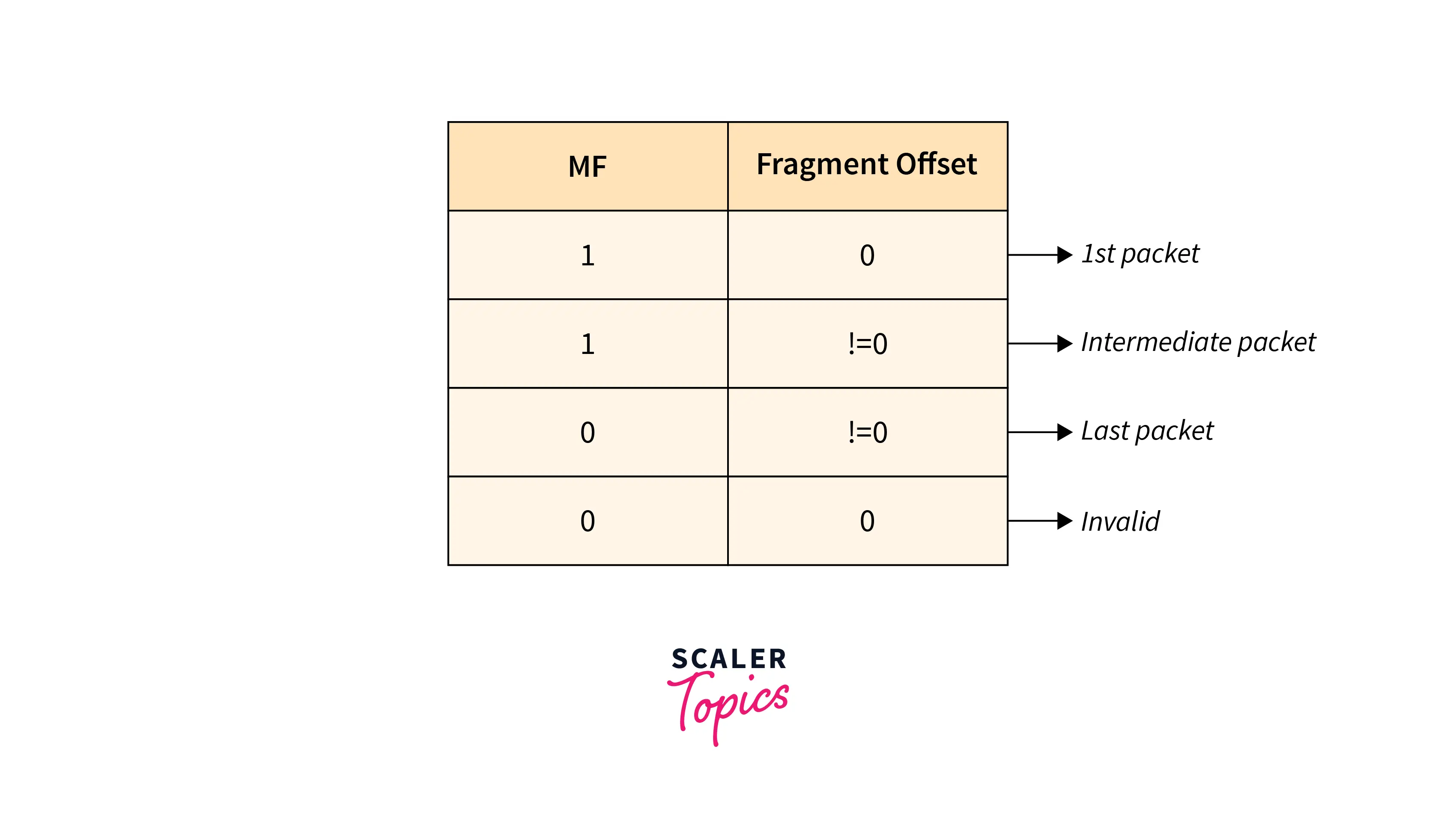
- The destination should be able to tell that the datagram is fragmented based on the MF, Fragment offset field.
- From the Identification field, the destination should identify all fragments belonging to the same datagram.
- Determine the first fragment (
offset = 0). - Using header length and fragment offset, identify subsequent fragments.
- Continue until
MF = 0.
Example:- An IP packet of 520 bytes with an IP header of 20 bytes was received by an IP router with a Maximum Transmission Unit (MTU) of 200 bytes. The values of the necessary IP header fields.
Solution:
- Since the MTU is
200bytes and the header size is20bytes, the maximum data length is180bytes. However, since this length cannot be expressed in a fragment offset since it is not divisible by8, the greatest length of data that is practical is176bytes. - The total number of fragments is
(520/200)which is equal to3. - Header length =
5(20/4Equals5because the scale factor is4). - e(efficiency) is given by (Data without header)/(Data with header) is equal to
500/560=89.2 %.
:::
:::section{.summary}
Conclusion
- Fragmentation is a process that divides packets into smaller pieces (fragments) so that the resulting pieces can travel across a link with a smaller maximum transmission unit (MTU) than the original packet size.
- The network layer fragments data when the maximum size of a datagram exceeds the maximum size of data that can be retained in a frame, i.e., its Maximum Transmission Unit (MTU).
RFC 791specifies IP packet fragmentation, transmission, and reassembly mechanism.RFC 815specifies a streamlined reassembly algorithm.- Fields in the IP header are:
- Identification Field (16 bits)
- Fragment Offset Field (13 bits)
- More Fragments Field (MF)
- Don’t Fragment Field (DF)
- A datagram is the smallest data transmission unit in a connectionless communication system. Datagrams are data packets that contain enough header information to be routed separately to the destination by all intermediate network switching devices.
- A node can prevent fragmentation of packets by setting the Don’t Fragment (DF) flag in such packets to
1. - Since packets take distinct paths (datagram packet switching), reassembly of Fragments only occurs at the destination and not at routers.
